Background
Evolution of Lower Limb Prostheses
The First Prosthetic Toe

(A New Look at an Ancient Egyptian Prosthetic Toe – The History Blog, 2017)
The first recorded use of a prosthetic toe is linked to Amenhotep II. This discovery highlights the early innovations in prosthetic development, even in ancient civilizations.
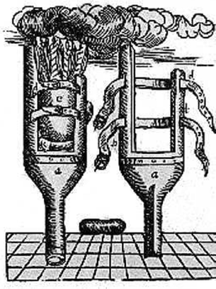
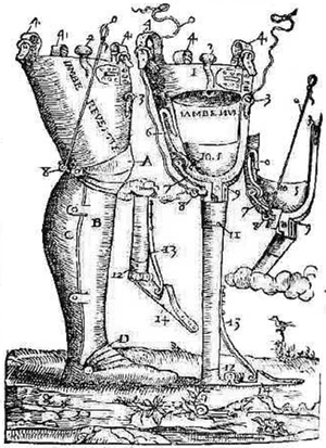
Ambroise Paré and the Birth of Mechanical Prosthetics
(Hernigou et al., 2013)
In the 16th century, Ambroise Paré, a French surgeon, revolutionized prosthetic design by introducing a mechanical knee that could lock when standing and bend at will. His innovations laid the foundation for future advancements in prosthetic limb development.
The First Mechanical Lower Limb Prostheses
(Hernigou et al., 2013)
The Industrial Revolution led to significant improvements in prosthetic technology. A major transformation occurred at the end of World War II, with the introduction of new materials and a deeper understanding of biomechanics.
Key Innovations
- Patellar-Tendon-Bearing (PTB) Prosthesis Socket (1950s) - Allowed for variations in materials and suspension techniques.
- Silicone Suction Socket (3S) (1989) - Improved suspension and total surface bearing.
- ICEROSS (Icelandic Roll On Silicone Socket) (1993) - Enhanced hydrostatic loading.
State of the Art: Materials and Manufacturing
(Sewell et al., 2000)
Modern prosthetics have undergone tremendous advancements, with traditional materials like metal, leather, and wood being replaced by:
- Thermosetting Resins & Thermoplastics - Used for lightweight and durable designs.
- Composites - Offering enhanced flexibility and strength.
- 3D Printing - Revolutionizing customization, affordability, and design.
Types of Lower Limb Prostheses
(Gehlhar et al., 2023)
1.1.1.1. Passive Prostheses
These are the most common and do not have active control mechanisms. They provide structural support but lack powered movement.

1.1.1.2. Powered Prostheses
These utilize sensors and microprocessors to provide adaptive control and stability. Some advanced models integrate with the nervous system, allowing for neural control.
1.1.1.3. Dual-Actuated Knee-Ankle Prostheses
Only a few models have transitioned from research to commercial availability, with just two currently on the market.
Want to learn more? Explore our Protocols & Methods section for detailed insights.
3D Printing Technique
3D printing, or additive manufacturing, creates objects layer by layer from a digital model. Appeared in the 1980s, it has revolutionized industries like healthcare and prosthetics by enabling rapid, cost-effective, and customizable production. There are several additive manufacturing techniques available such as selective laser sintering (SLS), fused deposition modelling (FDM), and stereolithography (SLA) (Rai et al., 2022). However, our project is focused on FDM technique which is a widely used 3D printing technique where thermoplastic filament is melted and extruded to build structures. Common materials include:
- Polylactic Acid (PLA): Biodegradable and easy to print.
- Acrylonitrile Butadiene Styrene (ABS): Strong but requires higher temperatures.
- Thermoplastic Polyurethane (TPU): Flexible and suitable for soft prosthetics.
- Polyethylene Terephthalate Glycol (PETG): Durable with balanced properties (Cano-Vicent et al., 2021).
Generally speaking, the fundamental idea behind the FDM production process is to simply melt the raw material and make it easier to create new shapes. The substance is heated to a semiliquid state by use of a filament coil on a wheel that is forced into a temperature-controlled nozzle. Layer by layer, the molten material is precisely extruded and guided by the nozzle to create a structural member. This mimics the contours of a layer that the application program has added to the FDM operating system (Cano-Vicent et al., 2021).
General summary of the FDM process (Cano-Vicent et al., 2021)
Applications in Prosthetics
FDM is used for:
- Custom sockets for better fit and comfort.
- Protective covers for aesthetics and support.
- Adapters and accessories for enhanced functionality.
Advancements like multi-material printing and reinforced filaments (e.g., carbon fiber PLA) improve strength and customization.
Future Prospects
FDM continues to evolve with better materials, higher resolution, and integration with imaging technologies. It plays a key role in making prosthetics more accessible, cost-effective, and personalized for amputees.
3D-Scanners
What is a scan?
A scan is a digital method to capture detailed information from an object, a surface or a body. It captures either shapes and/or internal structures.
Examples of Scans:
→ 3D scans: captures the geometry of an object to create a 3D digital model (used in design, like prosthetics)
→ Medical scans:
- CT (Computed Tomography) : X-ray-based images of body structures
- MRI (Magnetic Resonance Imaging): Magnetic field imaging for soft tissues
- Ultrasound: Uses sound waves to visualize internal structures
→ Image scans: captures physical documents as digital files using a flatbed scanner → Biometric Scans: fingerprint/ facial recognition for security applications (===Biometrics in Cyber Security===)
Evolution of 3D scanning :
Five thousand years ago, ancient Babylonians and Egyptians already employed triangulation techniques. About 2,400 years ago, Euclid and Archimedes laid the mathematical foundations of trigonometry. In the 17th century, Snell von Rojen explored the principles of optical triangulation.
Despite this long history, practical 3D scanners capable of capturing high-resolution 3D images were developed only around 35 years ago. Their emergence followed a decade of theoretical research, laboratory experiments, and prototypes, driven by advancements in image processing systems.
The earliest 3D scanning systems designed for industrial applications were primarily used for surface inspection, comparative measurements, and deformation analysis (see image below).
OptoSIS : Topometrical Surface Inspection System
3D Scanning Principle:
Although there are a wide variety of different 3D scanning techniques, they all rely on the same principles. All 3D scanners use a sensor, which can be a physical probe, a laser, or a light, to measure the distance between a camera and an object. In our case, the sensor is light.
3D scanners are able to identify 3D points, calculated from photos and depth measurements through triangulation, with each point appearing individually on the screen. Together, these 3D points form a point cloud. The process of extrapolating the shape of a subject from points is known as reconstruction.
Once the scanner has created the point cloud, it meshes it to turn it into a 3D model composed of surfaces. Meshing is essentially connecting the points in the point cloud to produce a complete model. A mesh is a set of vertices and faces, along with information about how the vertices make up the faces. Instead of valuing each point equally during the meshing process, we can deprioritize certain points to create a mesh that is not extremely complex and therefore easier to work with.
Finally, the mesh is textured. In the context of 3D scanning, texture refers to an image painted onto a service, and applying a texture to a surface is called texture mapping (see images below).
3D Scan of Lina's arm
The 3D scanning setup we used :
We used a structured light scanner, Structure Sensor 3 (check it here), which captures depth data using infrared light. The scanner projects a structured pattern of infrared light onto an object, and its infrared camera analyzes distortions in the pattern to calculate depth. By combining this data with the smartphone’s camera feed, the sensor generates highly accurate 3D models with precise X-Y-Z coordinates.
Structured light 3D scanning is fast, produces high-resolution scans, and is particularly well-suited for capturing detailed shapes, including human limbs.
We connected the Structure Sensor 3 to an iPhone 13 (see setup below). We also had to download three applications to make de 3D scanning :
- Structure Sensor Calibrator : Precisely align 3D depth from your Structure Sensor accessory to your iOS device's camera
- Scanner - Structure SDK : Capture objects in 3D with your Structure Sensor.
- Structure App : Supports original Structure Sensor (Structure Sensor 3).
Computer Aided Design (CAD) software is then used to process the 3D scan, where adjustments can be made to the geometry. In our case, we used mostly Autodesk Meshmixer and Autodesk Fusion 360. The resulting 3D model of the modified final prosthesis design can then be exported to a 3D printer.
About sensors
For the sensor, we used a tool called "Structure Sensor 3" (check it here), which, when connected to an iPad or iPhone with the appropriate application, allows scanning an object, surface, or body part.
References :
Lathouwers, E., Díaz, M. A., Maricot, A., Tassignon, B., Cherelle, C., Cherelle, P., Meeusen, R., & De Pauw, K. (2023). Therapeutic benefits of lower limb prostheses: a systematic review. Journal of NeuroEngineering and Rehabilitation, 20(1). ===https://doi.org/10.1186/s12984-023-01128-5===
Hernigou, P. (2013). Ambroise Paré IV: The early history of artificial limbs (from robotic to prostheses). International Orthopaedics, 37(6), 1195–1197. ===https://doi.org/10.1007/s00264-013-1884-7===
A new look at an ancient Egyptian prosthetic toe – The History Blog. (2017, June 21). ===https://www.thehistoryblog.com/archives/47762===
Sewell, P., Noroozi, S., Vinney, J., & Andrews, S. (2000). Developments in the transtibial prosthetic socket fitting process. Prosthetics and Orthotics International, 24(2), 97–107. ===https://doi.org/10.1080/03093640008726532===
FILLAUER CE, PRITHAM CH, FILLAUER KD (1989). Evolution and development of the silicone suction socket (3S) for below-knee prostheses.
J Prosthet Orthot 1, 92-103.KRISTINSSON O (1993). The ICEROSS concept: a discussion of a philosophy.
Prosthet Orthot Int 17, 49-55.RADCLIFFE CW, FOORT J (1961).
The patellar-tendonbearing below-knee prosthesis. Berkeley, CA: Biomechanics Laboratory, University of California.Gehlhar, R., Tucker, M., Young, A. J., & Ames, A. D. (2023).
A review of current state-of-the-art control methods for lower-limb powered prostheses. Annual Reviews in Control, 55, 142–164. ===https://doi.org/10.1016/j.arcontrol.2023.03.003===
Webmaster. (2020, May 28). Limb Prosthetics | Our services. Du Plessis and Thiebaut. ===https://dportho.co.za/services/limb-prosthetics/===
Rai, P., Jankiraman, V., Teacher, M., Velu, R., Kumar, S. A., Binedell, T., & Subburaj, K. (2022). Design and optimization of a 3D printed prosthetic socket for transtibial amputees. Materials Today Proceedings, 70, 454–464. ===https://doi.org/10.1016/j.matpr.2022.09.365===
Cano-Vicent, A., Tambuwala, M. M., Hassan, S. S., Barh, D., Aljabali, A. A., Birkett, M., Arjunan, A., & Serrano-Aroca, Á. (2021). Fused deposition modelling: Current status, methodology, applications and future prospects. Additive Manufacturing, 47, 102378. ===https://doi.org/10.1016/j.addma.2021.102378===
Bernd Breuckmann, 25 years of high definition 3D scanning: history, state of the art, outlook, DOI: ===http://dx.doi.org/10.14236/ewic/eva2014.31===
Farhan M, Wang JZ, Bray P, Burns J, Cheng TL. Comparison of 3D scanning versus traditional methods of capturing foot and ankle morphology for the fabrication of orthoses: a systematic review. J Foot Ankle Res. 2021. DOI: ===http://dx.doi.org/10.1186/s13047-020-00442-8===
What is 3D Scanning? – Definition, Advantages and Uses,
3D Sourced, ===read the article===
Different Imaging Tests, Explained, Inside View, ===read the article===Image scanner, Wikipedia, ===read the article===Biometrics in Cybersecurity, ===read the article===